
Stochastic Estimation Methods for Induction Motor Transient Thermal Monitoring Under Non Linear Condition
H. Mellah, K E. Hemsas, Stochastic Estimation Methods for Induction Motor Transient Thermal Monitoring Under Non Linear Condition, Leonardo Journal of Sciences (LJS), vol.11, no. 20, 2012.
Stochastic Estimation Methods for Induction Motor Transient Thermal Monitoring Under Non Linear Condition
Mellah HACEN1* and Hemsas KAMEL EDDINE2
1 Department of Electrical Engineering, Faculty of Engineering, University Ferhat Abbas of Setif Cité Maabouda, Route de Béjaia / 19000 / Algeria.
2 Automatic Laboratory of Setif, Electrical Engineering Department, University of Setif, Algeria.
E-mail*: has.mel@gmail.com*.
* Corresponding author: (213) 05 53 03 87 39; Fax: (213) 0 36 83 97 84
Abstract
The induction machine, because of its robustness and low-cost, is commonly used in the industry. Nevertheless, as every type of electrical machine, this machine suffers of some limitations. The most important one is the working temperature which is the dimensioning parameter for the definition of the nominal working point and the machine lifetime. Due to a strong demand concerning thermal monitoring methods appeared in the industry sector. In this context, the adding of temperature sensors is not acceptable and the studied methods tend to use sensorless approaches such as observators or parameters estimators like the extended Kalman Filter (EKF). Then the important criteria are reliability, computational cost ad real time implementation.
Keywords
Induction Motor; Thermal Modelling; Estimation Techniques; Thermal Monitoring.
Introduction
The energy conversion in an electrical machine is inevitably accompanied by losses of power which emerge in calorific form in the credits part is constrictive machine.
When stator winding insulation materials are heated beyond their temperature limits by excessive heat from motor losses, the winding insulation materials may experience accelerated and irreversible deterioration, resulting in reduced motor life or even total motor failure [1].
To prevent such excessive thermal stress and ensure continuous and reliable motor operation, the National Electrical Manufacturers Association (NEMA) has established permissible temperature limits for stator windings of induction machines based on their insulation classes [2].
It is commonly assumed that the motor’s life is reduced by 50% for every 10°C increase above its stator winding temperature limit. Therefore, an accurate estimate of the stator winding temperature is crucial in ensuring proper motor operation below its thermal limit. Aside from direct stator winding temperature measurement by means of a thermocouple or resistive temperature detector (RTD), the thermal model based and the induction machine parameter-based temperature estimators are two major techniques used in tracking the stator winding temperature [1].
Thermal Modeling Methods of EM
In literature specialized one can gathered the methods of thermal modeling of the machines electric under the three types following:
Simple Modeling for a Coarse Approach
One finds in the literature of many simple approaches in order to give bonds between the temperature to the stator and the temperature with the rotor. [3], [4] thus present an identification method of the rotor of electric resistance which does not make it possible unfortunately to consider stator electric resistance These articles propose two thermal approaches then to bind two resistances of the electric model:
1 The first method is based on the experiment of EDF which considers that the rotor has a temperature higher of 10C than that of the stator.
2 The second method, based on work of Kubota, gives a simple relation of proportionality between two resistances calibrated on the face values of the maker badge. One finds the method of the proportionality in other articles like [5].On the other hand, of later work were realized on model EDF and put a flat as for its validity for all the operating modes [6].
Fine Modeling for a Precise Thermal Cartography
It is based on the use of the finite element method with a model geometric and mechanics detailed.
|
|
|
Figure 1. Thermal cartography portion of an asynchronous machine, obtained by finite elements [9] |
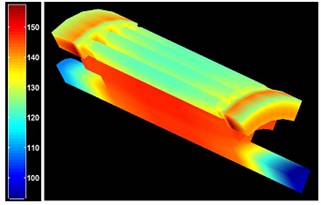
This makes it possible to obtain a complete cartography of the temperature of the machine (Figure.1). These results are very interesting since they make it possible to give an idea of the places where the temperature becomes critical according to the operations and answer the problems of the hot points [7, 8].
Electrical Equivalent Supply Networks (Nodal Method) [10] [11]
Those generally model the whole of the machine with nodes of temperature associated with each material used [12]. The identification of this model is thus carried out either by finite elements, or by a great number of points of temperature measurement within the machine. These models are generally very detailed (Figure 2) and thus too complex for our application in real time [12].
|
|
|
Figure 2. Equivalent thermal models of the asynchronous machine [12] |
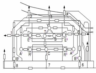
As our goal principal is the use of kalman filter, these two types of models are not exploitable, because these methods do not give the formalism of state.
Simplified Models
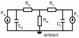
Other researchers sought to simplify the models by gathering the losses in subsets and by approximating the temperature in an unspecified point by a simple exponential answer which one can simply represent by a resistance and a heat capacity [13] and [14].
|
|
|
Figure 3. Thermal model of the asynchronous machine [13] |
Thermal Modelling of IM
In many cases the model is the familiar steady-state equivalent circuit, but for high performance drives a full transient model of the motor is required. Effective modeling, and therefore the effectiveness of drive control and estimation, is limited by the complexity of the physical processes occurring within the motor. Frequency dependence of the rotor electrical circuit, nonlinearity of the magnetic circuit, and temperature dependence of the stator and rotor electrical circuits all impact on the accuracy with which the motor can be modeled [15]. The modeling of the IM taking all the real behaviors without Assumptions simplifying being very difficult or impossible. For that one will suppose a model with simplifying assumptions. This paper addresses the third of these effects (temperature dependence) by incorporating a thermal model of the motor in the estimation process. The frequency dependence of the rotor electrical circuit and nonlinearity of the magnetic circuit are not included.
Temperature estimation in the induction motor has been dealt with by many authors see [11], but most of these publications describe either a very complex lumped-parameter network or the finite-element method.
A state-variable model of the induction motor is required for the EKF algorithm. The twin-axis stator reference frame [15] is used to model the motor’s electrical behaviour, because physical measurements are Made in this reference frame; the well-known linear relationship between resistance and temperature must be taken into account for the stator and rotor resistances

Or: Rs0, Rr0 stator and rotor resistance at the ambient temperature, αs and αr them coefficients thermal respectively. In the IM traditional models, one replace R1 and R2 by ![]() and
and ![]() respectively, what can be rearranged in space of state on the format:
respectively, what can be rearranged in space of state on the format:

![]()
The mechanical behaviour can be modeled by:
![]()
But the electromagnetic torque of the motor T can be represented in term of stator and rotor current components:
![]()
By equality of these two preceding equations, the equation speed of rotor in the space of state is:
![]()
The thermal model is derived by considering the power dissipation, heat transfer and rate of temperature rise in the stator and rotor. The stator power losses include contributions from copper losses and frequency- dependent iron losses [15].
![]()
Or: Kir is it constant of iron loss.
The rotor power losses are dominated by the copper loss contribution if the motor is operated at a low value of slip so:
![]()
Or: Hs, Hr are the stator and the rotor heat capacity respectively.
A simple representation of the assumed heat flow is given in Figure. 1. Heat flow from the rotor is either directly to the cooling air with heat transfer coefficient k2, or across the airgap to the stator with heat transfer coefficient k3
![]()
Heat flow from the stator is directly to the cooling air, with heat transfer coefficient k1
![]()
For an induction motor with a shaft mounted cooling fan, the heat transfer coefficients are dependent on the rotor speed. This dependence has been modeled approximately by a set of linear relationships

Or: k10, k20 and k30 thermal power transfer coefficients at the zero speed. k1w, k2w and k3w variation of thermal power transfer with speed.
Substitution into equations15 and 16 in the equations 13,14,17,18 and 19, and rearranging yields the thermal state equations for the stator and for the rotor:
![]()
![]()
The whole of preceding equations (6) a (9), (12), (20), and (21) gives us the model of following state:

Application of the EKF
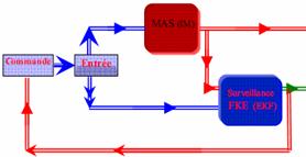
A reconstructor of state or estimator is a system having like entry, the entries and the exits of the real process, and whose exit is an estimate of the state of this process. The extended Kalman filter algorithm takes account of process and measurement noise in a general nonlinear system:

|
|
|
Figure 4. Application of EKF in IM |
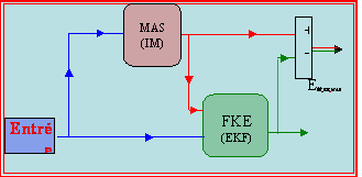
When: w(k) v(k) represents the process and measurement noise respectively.
A. The prediction stage is:

B. The correction stage is:

C. Covariance matrices initial Values
The matrix of covariance of error in estimation P and square of 7×7, translated the confidence which we can have in the adopted model, It is given [15] by:
![]()
The matrix of covariance of the noise of state Q quantifies the precision of the model and allows the dynamic adjustment of the parameters. It is generally difficult to determine because the direct observation of the state of the system is impossible, it is given in [15] by:
![]()
The matrix of covariance of noise of measurement R translated the level of noise to the measure it is given in [15] by:

Simulation Result
Constant Load
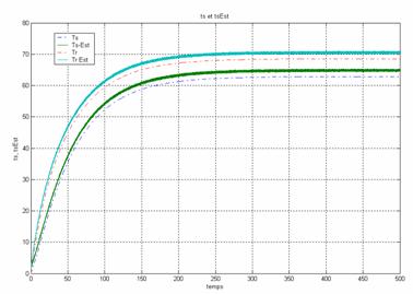
The two temperatures (thermal model and estimation) vary at different rates, Because of the differences in the losses, thermal capacities and the power transfer coefficients between the stator and rotor.
The stator and rotor temperature in the established mode reached the value 65°C, 72°C respectively but their value considered reached 62.3°C and 69.6°C.
Figure, 5 shows that deference between the rotor and the stator temperature is ≈10 C0 verified EDF experiment (The EDF experiment which considers that the rotor has a temperature higher of 10C C0 than that of the stator) [6].
|
|
|
Figure 5. The estimation and thermal model temperature of stator and Rotor result under the constant load condition |
Variable Load
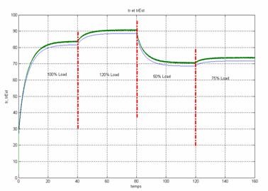
In order to verify the model performance for variable load, some step variations of load are applied (100% → 120% →50% → 75% of the rated load).
|
|
|
Figure 6. Stator temperature simulation result under the variable load condition |
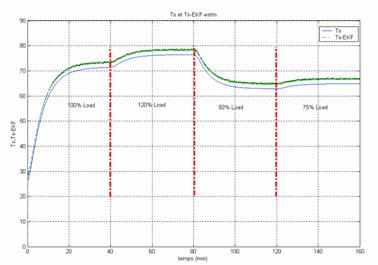
The Figure.6 and Figure.7 Show the simulation result of EKF and thermal Model temperature of stator and rotor winding under the variable load condition, the deference between the thermal model temperature and EKF is ≈2.4°C and ≈2.7°C for the stator and the rotor respectively.
|
|
|
Figure 7. Rotor temperature simulation result under the variable load condition |
Thermal Monitoring Based Model for Prevention of Heat Damage of Electric Motors
Basic assistance of this technique is the reference [16] where it is monitoring an internal temperature, but D. Staton [14] shows that the temperature distribution is not uniform and also the temperature more critical and restrictive and that of the windings. Our contribution is to exploit the help of Y. Huai [17] in the model presented in [15].
|
|
|
Figure 8. Diagram of simulation used to monitor the operation of the motor |
We need to determine how long the engine can operate in the given condition without exceeding the specified limit of temperature. To solve these problems we developed a program in Matlab / Simulink, which uses our thermal model. In Figure 8 we show a schematic diagram of simulation used to monitor the operation of the motor.
|
|
|
a) thermal monitoring of the stator temperature |
|
|
|
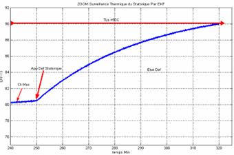
b- stator temperature (ZOOM) |
|
Figure 9. Thermal monitoring of the stator temperature |
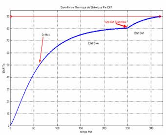
One applies torque intense and a stator defect to increase the stator temperature at limiting temperature TLS before the rotor temperature reaches the limit TLR (Figure. 9).
Under these conditions indicated above, the temperature in the stator winding temperature limit hit stator (TLS = 90°C) after 68min of engine operation (Figure. 9).
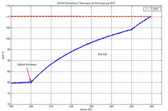
Figure 10 shows that we have applied a couple intense and a rotor failure at t = 200min to increase the rotor temperature to LRT, and we see that the temperature in the rotor winding reaches the limit temperature rotor (LRT = 110°C) after 90min of starting (Figure. 10).
|
|
|
a) thermal monitoring of the rotor temperature |
|
|
|
b) rotor temperature (ZOOM) |
|
Figure 10. Thermal monitoring of the rotor temperature |
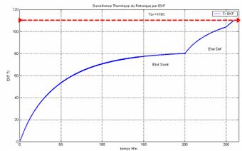
In both cases additional (TS = TLS or TR = TLR) and the engine will trigger the thermal protection of the windings is checked, so we will increase the life of the motor windings. This means that the engine should be operational for less than one 68 min to avoid overheating the stator and less than 58 minutes to the rotor.
Conclusion
Since the sensors can be not very reliable or expensive, the use of an estimator becomes necessary. The filter of Kalman makes it possible to achieve this goal, because it enables us to estimate and predict, simultaneously the temperature stator and rotor starting from the knowledge of the currents of food of various windings, which is well shown through the results of simulation obtained. The simulation study demonstrates that temperature rise calculation with simplified thermal model proposed in this paper is feasible. The error between the simplified thermal model proposed in this paper and the recent publications is acceptable. The simplified thermal model can be used to estimate both steady state and transient state temperature of key positions in high-speed generator. The overload running time calculation problem can be solved under the hot condition overload and cold condition overload. The simplified thermal model is also adapted to the various types of generator and motor, but modeling for different type generators and motor and calculating its model parameters are a hard work.
The use of EKF can not only estimate the stator and rotor temperatures but also allows us to perform a preventive monitoring technique based on the use of Matlab / Simulink, acting on the control of the power source.
The advantage of the thermal monitoring of IM and increased the life of insulation is therefore asynchronous.
References
1. Gao Z., Habetler T.G., Harley R.G., Colby R.S., An Adaptive Kalman Filtering Approach to Induction Machine Stator Winding Temperature Estimation Based on a Hybrid Thermal Model, IEEE, 2005.
2. Information Guide for General Purpose Industrial AC Small and Medium Squirrel-Cage Induction Motor Standards, NEMA Standard MG1-2003, Aug. 2003.
3. Beguenane R., El Hachemi Benbouzid M., Induction motors thermal monitoring by means of rotor resistance identification, Electric Machines and Drives Conference Record, 1997, p. TD2/4.1 - TD2/4.3.
4. Beguenane R., Benbouzid M.E.H., Induction motors thermal monitoring by means of rotor resistance identification, IEEE Transaction on Energy Conversion, 1999, 14(3), p. 566 - 570.
5. Sang-Bin L., Habetler T.G., Harley R.G., Gritter D.J., A stator and rotor resistance estimation technique for conductor temperature monitoring, Industry Applications Conference, 2000, Conference Record of the 2000 IEEE, 2000, 1, p. 381-387.
6. Saïd M.S.N., Benbouzid M.E.H., H–G Diagram Based Rotor Parameters Identification for Induction Motors Thermal Monitoring, IEEE Transactions on Energy Conversion, 2000, 15(1), 14-18.
7. Schöning M., Lange E., Hameyer K., Development and validation of a fast thermal finite element solver, Proceedings of the 2008 International conference on electrical machines, IEEE, 2008.
8. Sarkar D., Mukherjee P.K., Sen S.K., Use of 3-dimensional finite elements for computation of temperature distribution in the stator of an induction motor, Electric Power Applications, IEE Proceedings B, 1991, 138(2), p. 75-86.
9. Chauveau E., Contribution au calcul électromagnétique et thermique des machines électriques – Application à l’étude de l’influence des harmoniques sur l’échauffement des moteurs asynchrones, Thèse de doctorat de l’Université de Nantes, 2001.
10. Boglietti A., Cavagnino A., Staton D., Shanel M., Mueller M., Mejuto C., Evolution and Modern Approaches for Thermal Analysis of Electrical Machines, IEEE Transactions on Industrial Electronics, 2009, 56(3), p. 871-882.
11. Okoro O.I., Dynamic and thermal modelling of induction machines with non linear effects, Kassel University Press GmbH, Kassel, 2002, ISBN 3-89958-003-6.
12. Lazarevic Z., Radosavljevic R., Osmokrovic P., A novel approach for temperature estimation in squirrel-cage induction motor without sensors, IEEE Transactions on Instrumentation and Measurement, 1999, 48(3), p. 753-757.
13. Hurst K.D., Habetler T.G., A thermal monitoring and parameter tuning scheme for induction machines, Industry Applications Conference, 1997, Thirty-Second IAS Annual Meeting, IAS '97, Conference Record of the 1997 IEEE, 1997, 1, p. 136-142.
14. Moreno J.F., Hidalgo F.P., Martinez M.D., Realisation of tests to determine the parameters of the thermal model of an induction machine, Electric Power Applications, IEE Proceedings, 2001, 148(5), p. 393-397.
15. Al-Tayie J.K., Acarnley P.P., Estimation of speed, stator temperature and rotor temperature in cage induction motor drive using the extended Kalman filter algorithm, Electric Power Applications, IEE Proceedings, 1997, 144(5), p. 301-309.
16. Huai Y., Melnik R.V.N., Thogersen P.B., Computational analysis of temperature rise phenomena in electric induction motors, Applied Thermal Engineering, 2003, 23, p. 779-795.
17. Staton D., Hawkins D., Popescu M., Thermal Behaviour of Electrical Motors – An Analytical Approach, CWIEME 2009 Paper MDL [online] Available at: http://www.motor-design.com/downloads/CWIEME_2009_Paper_MDL.pdf.
Cited by
![]()
![]()

![]()

![]()
Date de dernière mise à jour : 03/08/2021
Ajouter un commentaire